I love my Archos JB6000. I mostly use it plugged into one of my home stereo systems or my car system. In these cases, it works and sounds great. Occasionally I use it with headphones directly. The headphones that are supplied with the unit are very efficient, and lightweight, but sound thin. I (and I'm sure everyone else) have to turn the bass control all the way up on the jukebox, and still it lacks bass. I also own a pair of Sennheiser HD414's. These are "real" headphones that have rich full sound when plugged into the Jukebox, but have one serious problem: The HD414s are probably the most inefficient headphones ever made, and thus the Jukebox can't even come close to produce enough volume for them. I also made a curious observation: My Sennheiser's are louder when plugged into my old portable CD player that runs from just 3 volts worth of batteries than the Jukebox which uses 5 volts. Since output power of an audio amplifier is directly proportional to the square of the power supply voltage the Jukebox should be over twice as loud as the CD player, not the other way around. I decided that there must be something fundamentally wrong with the audio output design of the Jukebox and decided to investigate it.
When I took the JB apart, I expected to find a small audio amp IC somewhere inside, what I found instead was that the headphones were driven directly from the Micronas DAC IC. I checked the data sheets for this IC, and sure enough, I found an ap-note where you can drive a pair of headphones directly from this IC. However the sample circuit showed a 47-ohm series resistor in the output circuit. Such a resistor with typical headphones will decrease the amplifier's output to much less than half power. I looked further and found they had another circuit where they drove a 32-ohm speaker in bridge mode across the two channels with no resistors. Driving a 32-ohm speaker in bridge mode is the same load on the IC as driving an 8-ohm speaker in "normal" mode. So why the 47-ohm resistor? I read further and found that Micronas made a big deal stating that this IC had no short circuit protection on its output stage, thus any short circuit could destroy the IC. I then checked the "absolute maximum ratings" page on this IC and with a few calculations, figured out that an 8-ohm load would be the lowest impedance that this IC could drive without exceeding its specifications.
Now back to the Jukebox. The ap-note really helped me trace the circuit in the Jukebox since it looked like Archos mostly copied the sample schematic including the 47-ohm series resistors in the output stage. Then I found something alarming. The output coupling capacitor seemed too small. I did not know what its actual value was, but I knew that it was much smaller than the 200 uf capacitor that would be required to deliver full bass response into a pair of headphones. My planned reduction of those 47-ohm series resistors would have made things even worse.
Typically as you plug and unplug headphones you momentarily short out the output of the amplifier. Also headphone cables often get damaged in a way that results in a short circuit. Even if I could find someone that would sell me a single-unit quantity of the Micronas IC, I don't have the soldering skill and equipment to successfully replace this 44 pin IC. Therefore I decided that I wanted to make sure the IC would never see less than an 8-ohm load if any output shorting occurred. To do this I planned to bypass the existing 47-ohm series resistors with common value 15-ohm resistors, which would result in about 11.3 ohms. This is still higher than the 8 minimum. So I could have gone lower, but considering that most headphones have at least 25 ohms of impedance those last 3 ohms would probably not make any significant improvement. You should be able to safely use a 10-ohm resistor, I just happened to have the 15s on hand. The harder task was what to do about the undersized output capacitors. Of course there is not a lot of room inside the Jukebox, and 200uf capacitors are big in comparison. I'm sure this fact is why there were undersized capacitors inside the unit in the first place. The largest value capacitor I was able to find that I figured I could squeeze into to jukebox was a 100uf 6-volt epoxy encased tantalum. Though not the 200uf I had hoped to fit in, my calculations showed that this still should get close to optimum bass performance with most headphones.
This operation is not trivial. There is lots of meticulous soldering and desoldering involved. If you have ask how to do this, you shouldn't attempt it. Good soldering/desoldering is a skill learned though practice. Don't trust anyone else that offers to do it for you unless you inspect their workmanship on simular parts. Sloppy workmanship here will result in a ruined Jukebox!
First remove the battery covers, and batteries. Then remove the 4 small phillips head screws from the top and bottom edges of the JB to remove the top cover. Then take the torx screws out of the sides of the unit, remove the bottom cover and corner bumpers, this part seemed to me to be harder to me than it should have been.
Bj?rn Stenberg has an excellent pictorial on how to get to this point Right Here .
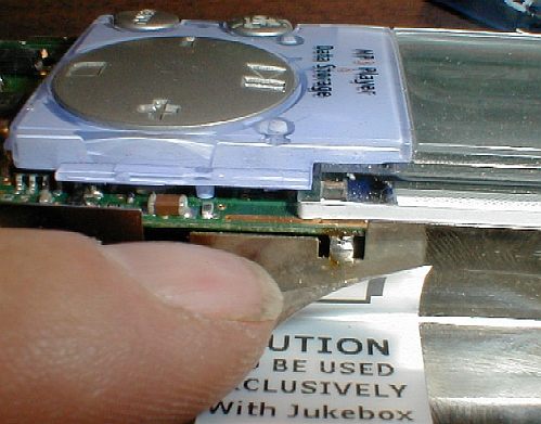
Then unplug the hard drive from the bottom of the unit and remove it.
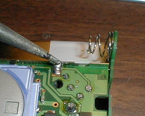
Now comes all the desoldering. You have to remove the battery compartment shields and the top battery contact circuit board from the main body of the unit. There are several places where you have to desolder things.
 Desolder the power connections from the top circuit board.
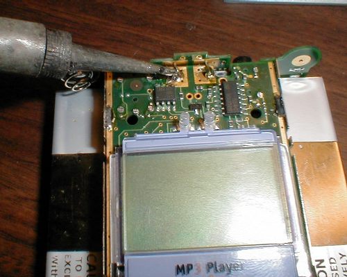
 Remove the top circuit board after also unsoldering the battery shields from both sides of it.
 Here are the last battery shield connections hidden under the labels on each side.
After you get all the points desoldered, you should be able to pull the battery shields and bottom circuit board from the main body of the unit.
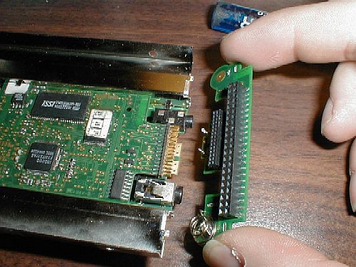
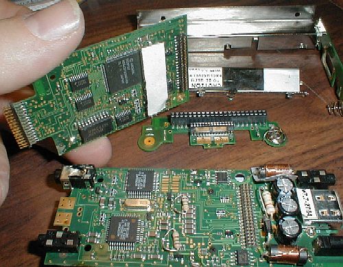 Next you have to remove the "daughter board" from the main circuit board.
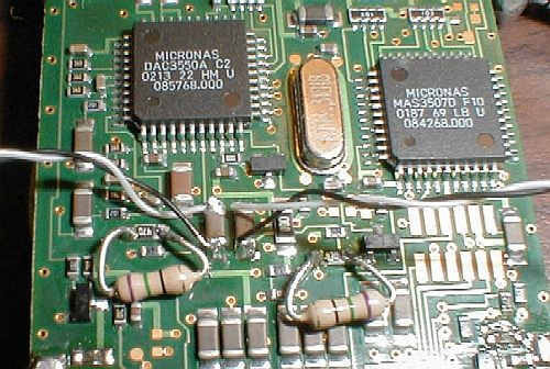
This finally exposes the portion of the circuit that we need to modify.
Next you have to remove the "daughter board" from the main circuit board.
This finally exposes the portion of the circuit that we need to modify.
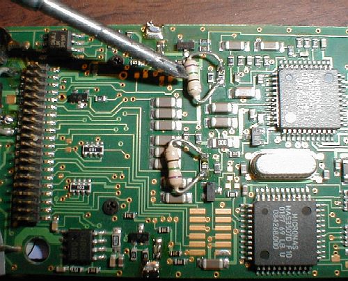 Notice in the pictures that I already bypassed the 47-ohm surface mount resistors with my, huge in comparison, 1/4th-watt 15-ohm resistors.
 The new resistors are positioned such that with the daughter board back in place, there is no chance something could short out.
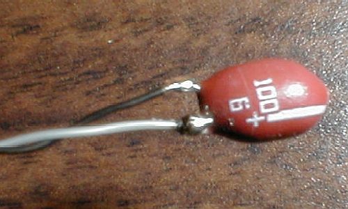 Next we have to prepare the 100uf 6-volt tantalum capacitors; I cut the leads very short so that I can have insulated "wire-wrap" wire leading up to the body of the device. These capacitors are polarized and in my case I wired to black wire to the negative terminal.
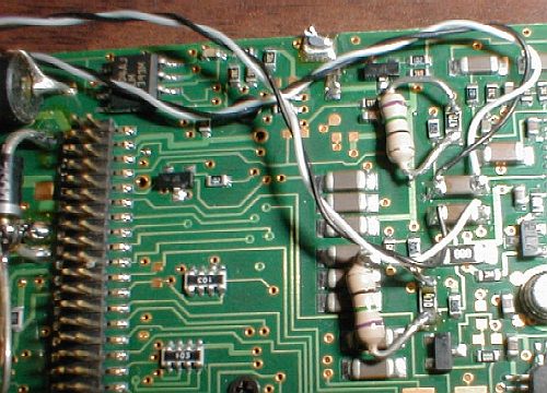
 Here we have the leads from my 100uf capacitors paralleled across the original undersized capacitors.
Notice in the picture, which side of the original capacitor the other ends of the black wires go. To insure correct polarity, it is very important that these wires connected this way.
 Just another view
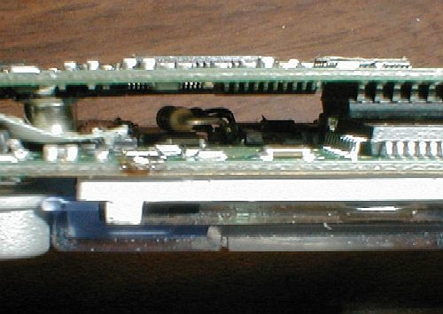
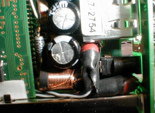 Finally, the only place I could find to put the capacitors was around the power connector. I wrapped them crudely in electrical tape to prevent shorting. I would have used heat shrink tubing here except that the tubing is thicker which would result in the capacitors not fitting in this area. Tape is ugly, but it worked.
While reassembling the unit, make sure nothing pinches through the thin insulation on the wire-wrap wire leading to the capacitors.
When I reassembled the unit it and powered it up, the first amazing thing that happened was that it worked despite all the butchering I just did to it. The volume was, as expected much louder. With the Archos supplied headphones, it was almost painful at full volume. With my Sennheisers, the volume was now usable, but still not great. have since gone to a pair a Radio Shack Optimus/Nova-44's that I repaired after rescuing from a client's garbage can (yes, I'm cheap!). These normal and average headphones work and sound great with the JB. Quantitatively, I believe that where full volume was before is now where 3/4 volume is now. Improved bass? Same thing, only better. Not only is there a good 25% more bass as displayed on the bass level control on the JB, but it is better bass! With the original Archos headphones the bass now seems to extend down another octave. Although these headphones are incapable of producing "true" bass, that extra octave made the difference allowing me to finally enjoy listening to my JB using these headphones. Using "real" headphones, the bass response sounds "normal" with the bass control advanced just one position from the "flat" or middle position. The response also extends deeper than before. What's more, transients in the music seem more dynamic. I'm sure this is because of the improvement that my modifications made to the damping factor of the amplifier, as well as extending the low frequency response. As expected, these modifications made no difference when I operated the unit with an external amplifier using the headphone output of the JB. The reason is while the impedance (a measurement inverse to the load amplifier load) of the headphones is around 25 ohms or so, the impedance of a typical amplifier input circuit is over 5000 ohms. At this impedance the original 47-ohm series resistors and small coupling capacitors are insignificant.
No, I am not interested in modifying your JB for you, experiencing this once was scary enough for me!
After this page was originally created, newer Archos products were released. It turns out that the products from the recording models on up do not have this final amplifier stage problem.
Here are some comments I've received concerning this web page so far.
Also HERE might be a case where I re-invented the wheel. It is very good page done by another that describes the same modification except without adding the resistors for more volume. It has very good pictures of the process however and uses better shaped surface mount type capacitors.
Page last modified Apr 19, 2003 by James Stewart and can be considered in the public domain